Battery Pack Pressure Relief Valves: How They Work and How to Size One
The function and construction of a battery pack pressure relief valve, the constraints that set its opening pressure and flow capacity, and why steady-state permeability data does not resolve the sizing question.
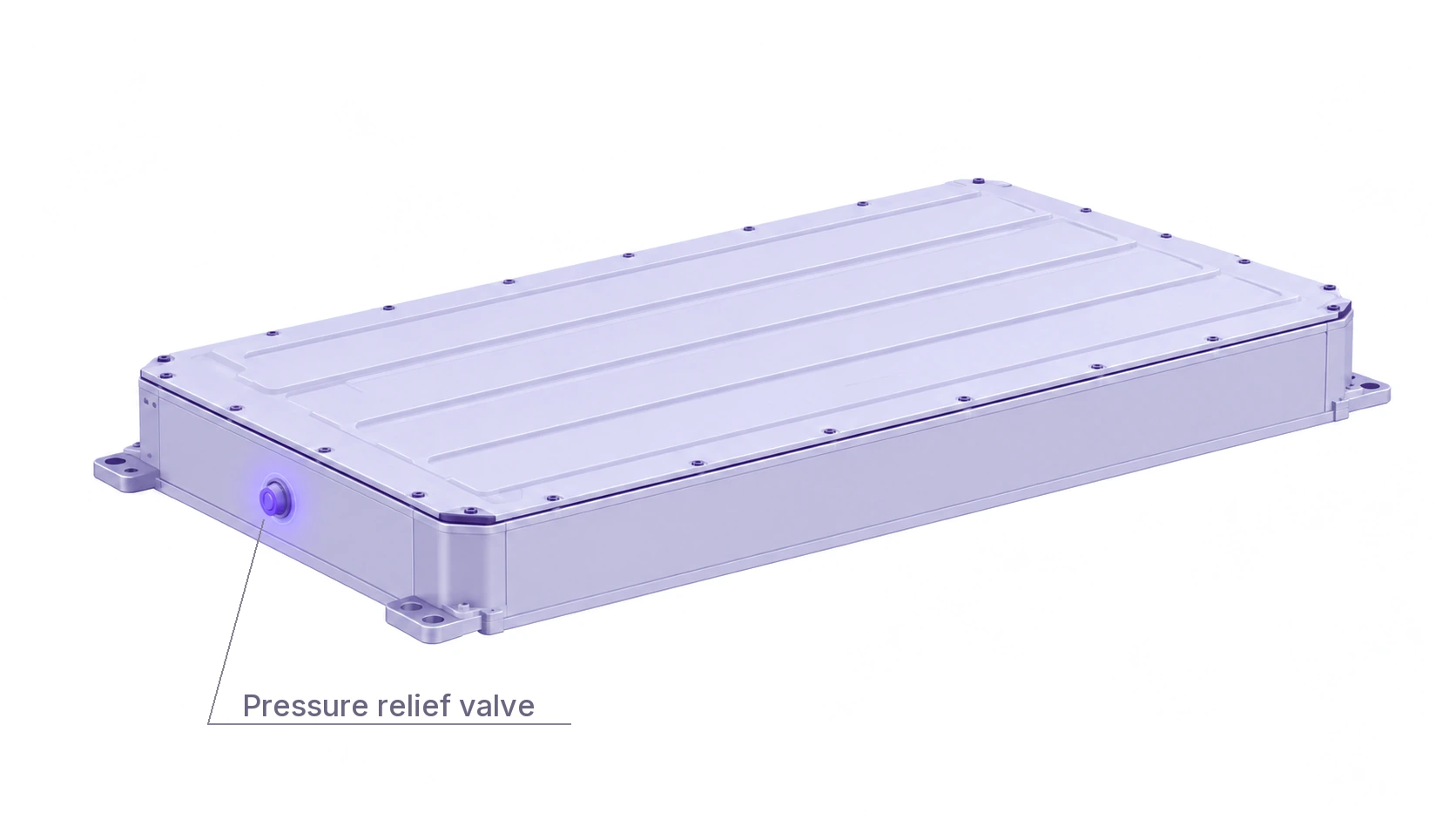
A pressure relief valve (PRV) in a lithium-ion battery pack is a safety device fitted to the enclosure wall. It equalises the pressure difference across that wall during normal service and opens a large-area exhaust path when the internal pressure exceeds a predetermined threshold. The same class of component is also designated an explosion-proof valve, a pressure relief vent, or a breather valve.
This article describes the function and construction of the device, the two operating regimes it must serve, the principal design variants, and the constraints governing its mounting position. It then addresses the selection problem: identifying a specific valve for a specific enclosure, and why the permeability data published on a supplier datasheet is insufficient to resolve that question.
What Is a Pressure Relief Valve in a Battery Pack?
A battery enclosure is subject to two requirements that act against each other.
The first is sealing. Cells, busbars, and control electronics require protection from water, particulate contamination, and corrosive road salt, and the ingress protection (IP) rating specifying that protection forms part of the vehicle or energy storage system requirement.
The second is tolerance of pressure differentials across the enclosure wall. Some of these arise in normal service: charge and discharge cycles heat the gas within a closed volume, cooling contracts it, and changes in altitude alter the external ambient pressure. Others do not. A cell undergoing thermal runaway discharges a large volume of hot, flammable gas into that same closed volume over a period of seconds.
A fully sealed enclosure satisfies neither requirement. Repeated pressure cycling degrades the seals until they leak, and a thermal runaway event has no available exhaust path. The pressure relief valve resolves the conflict: it maintains the seal and equalises slow pressure differentials during service, and it opens a wide exhaust path once the internal pressure exceeds its setpoint.
What a Battery Pack PRV Is Made Of
Pack-level valves are generally constructed from four elements.
The housing. Stamped steel, aluminium, or engineering polymer, mounted through the enclosure wall. It provides the mounting interface and shields the internal components from stone impact and debris.
The permeable membrane. Expanded polytetrafluoroethylene (ePTFE), drawn into a microporous structure whose pore dimensions are substantially larger than a gas molecule and substantially smaller than a liquid water droplet. Gas passes through the membrane freely; liquid water does not, because surface tension retains droplets on the outer face rather than permitting them to wick through. This element allows a sealed enclosure to equalise pressure without forfeiting its ingress protection rating, and it must continue to do so for the service life of the pack. The material is therefore selected for chemical and thermal stability rather than for cost.
The relief mechanism. A spring-loaded plug, or a diaphragm configured to rupture. This element remains closed throughout every normal pressure excursion and opens only once the setpoint is exceeded.
The seals. O-rings and gaskets between the valve body and the enclosure, which prevent leakage around the perimeter of the assembly itself.
Figure 1 separates the assembly along its axis. The four elements above are functional groupings rather than individual parts, and a typical spring-operated valve resolves them into seven: the gas film sits directly beneath the valve cap, so that the equalisation path is the shortest one through the device, while the spring, plug and sealing ring occupy the body above the valve seat.
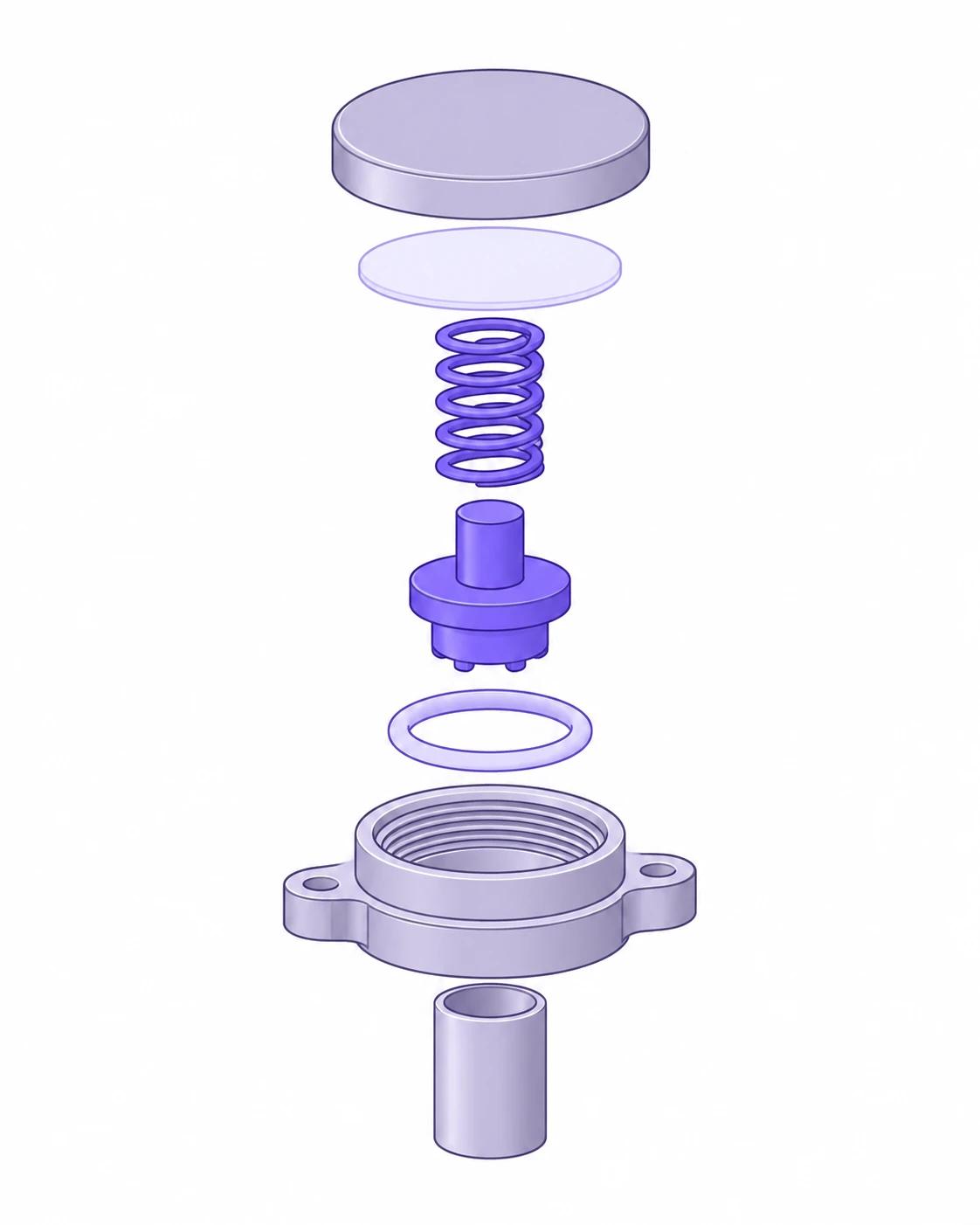
- Valve cap
- ePTFE permeable membrane
- Spring
- Valve plug
- O-ring seal
- Threaded valve seat
- Spring shield
How Does a Battery Pack PRV Work?
The valve operates in two regimes, separated by orders of magnitude in both volumetric flow rate and duration.
Pressure equalisation, continuous. Gas traverses the membrane in whichever direction the pressure differential requires. The differentials involved are small and develop slowly, over minutes to hours, driven by temperature change within the enclosure and by ambient pressure change outside it. Atmospheric pressure decreases monotonically with altitude, so a vehicle ascending a mountain pass subjects the enclosure to an increasing internal pressure differential even at constant temperature. This regime is active whenever the pack is in service.
Emergency venting, single event. When a cell enters thermal runaway, gas is generated at a rate far exceeding what the membrane can pass. The internal pressure crosses the setpoint, the relief mechanism opens, and a full-bore exhaust path supersedes the membrane as the route out of the enclosure. This regime may never be invoked during the service life of a pack, and where it is invoked, it persists for seconds.
The engineering difficulty is that a single component must serve both regimes, and the two impose opposing requirements upon it.
Types of Battery Pack Pressure Relief Valve
For selection purposes the governing distinction is not the actuation mechanism but whether the valve is capable of reclosing after it has opened.
| Spring-loaded valve | Pin-pierced diaphragm valve | |
|---|---|---|
| Actuation | Gas pressure displaces a plug from its seat against a spring | The diaphragm deforms outward under internal pressure until it is punctured against a fixed pin |
| Following actuation | The spring reseats the plug once pressure falls, restoring the seal | The flow path remains open for the remainder of the event |
| Within a single event | Capable of repeated opening and reclosing | Actuates once |
| Ingress protection rating | Retained | Forfeited |
| Serviceability | Reusable | Requires replacement after actuation |
Burst discs belong to the second category, but they are predominantly a
cell-level device, in which a scored element in the cell casing ruptures once to
prevent the cell itself from bursting. At pack level the non-reclosing
equivalent is typically a pin-pierced diaphragm, which vents in under one second
and presents a large flow area, at the cost of being a single-use component. For
the purposes of a pressure calculation the two are equivalent, which is why
ThermoSketch PRV-Sizing, a simulation tool for pack
pressure during a venting event, reduces the full taxonomy to two valve types,
Spring and Membrane.
This reduction is not a simplification adopted for convenience. Whether the valve recloses determines the form of the pressure history after the setpoint is crossed, and it is the only property of the actuation mechanism that does so.
Why a Stronger Enclosure Is Not an Alternative
The apparent alternative is to omit the valve and construct an enclosure capable of containing whatever occurs within it. This approach fails for two independent reasons.
The first concerns the gas itself. Thermal runaway proceeds as a chain of reactions rather than as a single event. The passivation layer at the anode decomposes first; the separator subsequently loses integrity and internal short-circuiting intensifies; finally the cathode decomposes, releasing oxygen, while the electrolyte decomposes in bulk. Each stage generates gas more rapidly than the preceding one. The product is a mixture of hydrogen, carbon monoxide, carbon dioxide, and light hydrocarbons, both toxic and flammable, evolved in a quantity determined by the cell rather than by any parameter available to the enclosure designer. Containing that quantity requires the enclosure to be designed as a pressure vessel, at a mass and cost no vehicle programme will accept, and the result is a vessel filled with flammable gas.
The second concerns normal service. Air carries moisture, and warm air carries more of it than cold air. An enclosure sealed at elevated temperature and subsequently cooled will condense the difference onto its internal contents, which in a battery pack comprises busbars, connectors, and insulation. An enclosure able to equalise with ambient conditions transports that moisture back out; a fully sealed enclosure accumulates it.
Regulation has converged on the same conclusion. GB 38031-2025 raises the requirement from survivable occupant escape to no thermal runaway propagation, and introduces a criterion prohibiting visible smoke from entering the passenger compartment. UN 38.3 and ECE R100 both treat a calibrated relief path as a precondition for approval rather than as an optional provision.
Where Should a PRV Be Mounted?
Mounting position is constrained before flow capacity is.
The exhaust must not be directed toward the passenger compartment, nor toward an adjacent pack. The valve belongs high on the gas flow path, since the evolved gas is hot and therefore buoyant, and a valve positioned below the accumulating gas will not evacuate the enclosure efficiently. It should not occupy the lowest point of the enclosure, where it may be submerged or subjected to direct high-pressure washing. It also requires an unobstructed zone, clear of cooling manifolds and structural ribs that would impede the exhaust or compromise the sealing face.
These are not discretionary preferences. Song et al. (2024) demonstrated numerically that relocating the valve on an otherwise identical pack altered both the peak overpressure within the enclosure and, more markedly, the loading imposed on adjacent packs.
Figure 2 shows the arrangement those principles imply. The evolved gas rises from the venting cell, accumulates beneath the lid, and reaches the valve at the highest point of that path.
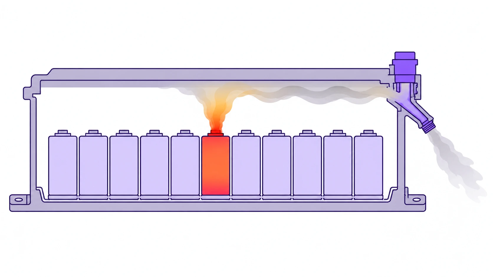
- Cell in thermal runaway
- Evolved gas accumulating beneath the lid
- Pressure relief valve at the high point of the gas path
- Exhaust directed downward and outboard
Vehicle packaging rarely permits that arrangement. The upper face of a traction battery pack sits directly beneath the vehicle floor, with a clearance measured in millimetres, so there is room neither for a valve body on the lid nor for its exhaust to escape. Production valves are consequently mounted in a side wall and vent approximately horizontally, outboard. The principle survives in weakened form: the valve goes as high in the side wall as the mounting flange and sealing face allow, and the gas that collects in the last few millimetres beneath the lid is gas the valve will never see. The freedom of position evaluated numerically by Song et al. is more readily available in an energy storage cabin, where the packs are free-standing, than in a vehicle.
Recurring Errors in PRV Selection
The foregoing is component-level knowledge, and it is approximately where the available literature on this subject terminates. The more demanding problem is matching a specific valve to a specific enclosure, and four failure modes recur.
The Opening Pressure Window Is Narrower Than It Appears
The setpoint is constrained from both directions.
It is bounded above by the enclosure. The valve must open below the pressure at which the enclosure ceases to perform its function, which is not the pressure at which it ruptures. Deformation sufficient to breach a seal or close a busbar clearance already constitutes failure, and it occurs well before rupture.
It is bounded below by normal service. A setpoint positioned close to the routine pressure excursion will be crossed by temperature and altitude variation alone. The valve then actuates in the absence of any fault, which on a non-reclosing device renders it expended, and on any device admits dust and water into the enclosure.
The interval between these bounds is narrower than most initial estimates suggest, and it is determined by enclosure structural analysis rather than by a product catalogue.
The Valve May Never Experience the Design Pressure
Song et al. (2024) conducted an overcharge test on a commercial liquid-cooled pack fitted with a relief valve to specification. The cell safety vent opened. Within the following minute the pack exploded, deforming the lid and ejecting fasteners. The relief valve did not open, and it was not defective.
Two mechanisms combined. The light gases evolved early, among them hydrogen and carbon monoxide, passed directly through the permeable membrane and dissipated the pressure differential, so the setpoint was never approached. The electrolyte subsequently vaporised, and vaporised electrolyte does not traverse the membrane at all: the droplets exceed the pore dimensions, and the material repels them. The species responsible for the explosion was precisely the one the membrane retained within the enclosure.
The conclusion generalises beyond that particular pack. A pressure-flow characteristic is measured on a clean valve passing clean gas. It is the appropriate basis for a calculation, and it is not a guarantee of in-service behaviour.
A Spring-Loaded Valve Does Not Behave as a Switch
Wang et al. (2026) derived, from a force balance on the valve plug, that the opening pressure of a spring-loaded valve is necessarily higher than its closing pressure. This is a consequence of the structure rather than a manufacturing tolerance, and it means that every spring-loaded valve exhibits a pressure hysteresis band.
The practical consequence is intermittent venting. Where gas is evolved slowly enough that the internal pressure falls below the closing threshold between successive deliveries, the valve reseats and subsequently reopens, cycling many times across a single thermal runaway event rather than venting once. Their instrumented pack test recorded this behaviour directly.
A valve represented as opening at a single pressure predicts neither the peak nor the exhaust profile of a valve that behaves in this manner.
Vent Area Exhibits Diminishing Returns
The same study examined valve size numerically. Increasing the relief path from an inadequate area to an adequate one reduced the peak internal overpressure by approximately an order of magnitude. A further increase in size produced a considerably smaller reduction. The return on vent area saturates, and beyond that point the effective design variables are the setpoint, the number of valves, and the direction of the exhaust, rather than additional area.
Why Equal Total Gas Does Not Imply an Equal Sizing Problem
Peak pressure within the enclosure is not determined by the quantity of gas a cell evolves. It is determined by the rate at which that gas is delivered, evaluated against the volumetric flow the valve can pass at the pressure differential prevailing at that instant. Pressure rises while gas is delivered faster than the valve can evacuate it, and it reaches a maximum at the moment those two rates balance.
Cell chemistries differ in gas evolution kinetics, not only in gas evolution quantity. Two cells may deliver comparable total gas into an enclosure while one does so as a short, violent release and the other distributes it over a substantially longer interval. Figure 3 contrasts the two: the curves converge on a comparable total, but the gradient that the relief valve must contend with differs by a large factor throughout the early part of the event. These constitute different sizing problems, and the more rapid release is the more demanding case even where it evolves less gas in total.
A second consequence follows, and it governs which valve is appropriate rather than how many. A rapid evolution requires a valve that reaches useful flow immediately above its setpoint, since there is insufficient time for pressure to climb into the productive region of the characteristic. A gradual evolution is precisely the case in which a spring-loaded valve may reseat and cycle, so its hysteresis band ceases to be a secondary consideration and begins to govern the result.
Neither behaviour can be obtained from a steady-state permeability table. Both follow from integrating the problem through time.
Defining the Sizing Question
The volumetric flow the valve passes is obtained from its characteristic at the prevailing pressure differential; which branch of that characteristic applies depends on whether the valve is currently open, which in turn depends on the pressure that the flow is itself determining. This circularity constitutes the principal difficulty. The problem is coupled, and it does not reduce to a division.
It follows that sizing is an imprecise designation for the exercise. For an enclosure already defined, the task is not to solve for a dimension. It is to select among commercially available components whose setpoints and flow characteristics the manufacturer has already fixed, and the available degrees of freedom are exactly two: which valve is fitted, and how many.
Void volume, the venting curve, the number of cells assumed to vent simultaneously, and the enclosure pressure limit constitute the question. Adjusting any of them until a candidate passes modifies the question rather than answering it.
How ThermoSketch PRV-Sizing Addresses It
ThermoSketch PRV-Sizing integrates the coupled problem described above, permitting commercially available candidate valves to be screened against a fixed venting scenario.
Inputs. Enclosure void volume, ambient pressure and temperature, a cell venting curve, the number of cells venting simultaneously, the enclosure pressure limit, and a candidate valve specified by its opening pressure and its flow characteristics before and after actuation. Cells and valves may be drawn from the built-in databases or supplied as measured data in CSV format. Values may be entered in whatever unit the source data already uses.
Outputs. The complete pressure history, the peak in both absolute and gauge terms, whether the valve opened and the time at which it first did so, and a pass or fail assessment against the specified limit. Temperature, gas quantity, volumetric flow rate, and valve state are plotted alongside, which permits the user to establish whether the valve is controlling the event or merely present during it. Results are exportable to CSV and to a PDF report suitable for design review.
Limitations. We treat the gas inside the enclosure as a single lumped-parameter volume. We do not model the pressure equalisation regime, combustion or ignition, or anything downstream of the valve outlet, and we do not model the membrane blockage described above. The tool establishes whether a given valve holds a given enclosure below a given limit, and nothing beyond that. We set out every simplification, and the direction in which each one biases the result, in Assumptions and Limits.
We do not retain simulation inputs or results on our servers. Saving a project writes a JSON file to local storage, which is material where the venting curve under consideration constitutes proprietary cell test data. Our security page records what is and is not retained.
Conclusion
A relief valve is a small component carrying a disproportionate share of the safety case for a battery pack. Most of what determines whether it performs is settled before any catalogue is consulted: the pressure the enclosure can sustain, the rate at which the cells evolve gas, and the number of cells that must be assumed to vent simultaneously.
Once those are established, commercially available components can be screened against them. The procedure is set out in the sizing workflow, and ThermoSketch PRV-Sizing provides sample cells and valves against which measured data may be substituted as it becomes available.
References
Song, Y., Hou, J., Lyu, N., Luo, X., Ma, J., Chen, S., Wu, P., Jiang, X., and Jin, Y. (2024). Electric-controlled pressure relief valve for enhanced safety in liquid-cooled lithium-ion battery packs. Journal of Energy Chemistry, 90, 98-109. https://doi.org/10.1016/j.jechem.2023.11.007
Wang, P., Liu, L., Xu, C., Liu, Y., Zheng, T., Liu, L., Li, J., Guan, D., Jiang, F., Feng, X., and Ouyang, M. (2026). A multiphysics study on venting safety in battery energy storage systems: from cell venting to energy storage station explosion hazards. Energy, 344, 139870. https://doi.org/10.1016/j.energy.2025.139870
Neither study describes the PRV-Sizing implementation, and neither constitutes an endorsement of this tool. Further context on the use made of each is given under Further Reading.
Frequently Asked Questions
What is the difference between a cell safety vent and a pack pressure relief valve?
They are distinct devices with opposing reset behaviour. A cell safety vent is located on the cell casing, ruptures once, and does not reclose. A pack pressure relief valve is located on the enclosure wall, opens above a setpoint, and in a spring-loaded type recloses below it. The cell safety vent is the source of the gas; the pack pressure relief valve is the component being selected.
What pressure should a battery pack PRV open at?
No catalogue value applies, because the setpoint is bounded by the enclosure on one side and by the duty cycle on the other. It must open below the pressure at which the enclosure ceases to seal, which is lower than the pressure at which it ruptures, and above the largest differential that routine temperature and altitude variation will produce. It is an output of structural analysis rather than a selection from a list.
Can a battery pack PRV be reused after it opens, and what happens to the ingress protection rating?
This depends on whether the valve recloses. A spring-loaded valve reseats as pressure falls and restores the seal, so the ingress protection rating is retained. A pin-pierced diaphragm leaves the flow path permanently open, so the enclosure is no longer sealed and the valve requires replacement before the pack returns to service.
Which standards require a pressure relief valve on a battery pack?
GB 38031-2025 raised the requirement from survivable occupant escape to no thermal runaway propagation, and introduced a criterion prohibiting visible smoke from entering the passenger compartment. UN 38.3 and ECE R100 both treat a calibrated relief path as a precondition for approval. None specifies a component. What is required is evidence that the relief path performs, which constitutes a calculation and a test rather than a procurement decision.
Where should a PRV be mounted on a battery enclosure?
High on the gas flow path, since the evolved gas is hot and therefore buoyant. Directed away from the passenger compartment, normally downward or outboard. Clear of the lowest point of the enclosure, where it could be submerged, and clear of cooling manifolds and structure that would obstruct the exhaust. Position measurably alters both the peak pressure within the enclosure and the loading on adjacent packs.
What data is required to size a battery pack pressure relief valve?
Seven inputs. Enclosure void volume with cells and internal components subtracted, ambient pressure and temperature, the cell venting curve together with its provenance, the number of cells assumed to vent simultaneously, the enclosure pressure limit, the candidate valve opening pressure, and its pressure-flow characteristics before and after actuation. ThermoSketch PRV-Sizing accepts precisely this set, and any element of it may be supplied as measured data rather than drawn from a library.
Can battery pack vent requirements be calculated by hand?
Not for the thermal runaway case. The flow through the valve depends on the pressure differential, the pressure depends on the quantity already evacuated, and which branch of the flow characteristic applies depends on whether the valve has opened. That coupling requires integration through time. The steady-state flow values published on a supplier datasheet are characterised for the pressure equalisation regime and address a different question. ThermoSketch PRV-Sizing integrates the thermal runaway case directly.
Do lithium iron phosphate and nickel-cobalt-manganese packs require different pressure relief valves?
Frequently yes, though not for the reason commonly assumed. Lithium iron phosphate (LFP) and nickel-cobalt-manganese (NCM) chemistries differ in the rate at which gas is evolved, not only in the quantity, and peak pressure is governed by rate rather than by total. A more gradual evolution may additionally permit a spring-loaded valve to reseat and cycle, which alters the result further. Whether a valve qualified on one pack covers another is established by running both venting curves, not by comparing chemistry designations.